

Last updated: October 2, 2026
Quick answer: A controller deadzone defines the physical movement range a thumbstick must cross before the game registers motion. Setting the deadzone balances immediate input response against stick drift prevention. The hardware constraint stems from mechanical spring centering tolerance and potentiometer wear inside the controller chassis.
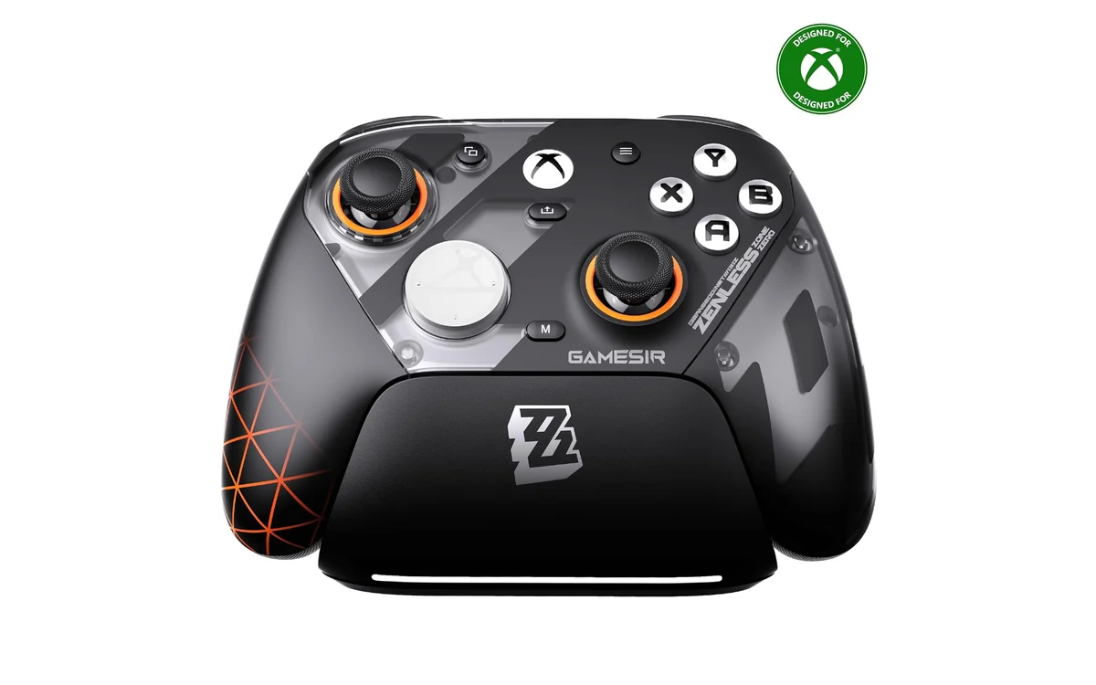
Short answer: A controller deadzone defines the software-ignored physical movement area around the thumbstick’s neutral center or outer perimeter. Gamers configure deadzones to eliminate stick drift caused by worn potentiometers while retaining micro-aim accuracy. Proper calibration requires tuning hardware Analog-to-Digital Converter (ADC) values through driver software or game engines.
Understanding controller deadzones helps players optimize aim precision across modern titles in October 2026. Thumbsticks rely on mechanical potentiometers or Hall effect magnetic sensors to translate physical displacement into coordinate values. When thumbsticks rest at center, mechanical tolerances prevent exact zero readings. Deadzone settings establish a computational threshold where micro-movements remain suppressed until deliberate force moves the stick past the boundary line.
What Is Controller Deadzone Explained?
Thumbstick deadzone represents an unresponsive zone programmed into the input processing pipeline. Thumbstick output maps onto a coordinate system across horizontal (X) and vertical (Y) axes. The rest state generates raw voltage values read by the microcontroller ADC. Mechanical springs never return the stick module to the mathematical center (0,0) after deflection. Residual offset registers as phantom movement without a software deadzone filter.
Deadzone configuration separates into two primary thresholds: inner deadzone and outer deadzone. The inner deadzone surrounds the central rest point. The outer deadzone defines the perimeter threshold beyond which input registers maximum 100 percent deflection. Confusing deadzone with sensitivity causes calibration errors; sensitivity adjusts the cursor acceleration curve after the stick leaves the deadzone boundary, whereas deadzone dictates the exact point where registration begins.
Why Controller Deadzone Explained Matters
Deadzone size directly controls the trade-off between target acquisition speed and mechanical error suppression. First-person shooter (FPS) titles demand small inner deadzones for instant micro-adjustments during long-range gunfights. A large inner deadzone creates a feeling of input delay: the thumb moves, the reticle remains stationary until the stick passes the deadband threshold, then the crosshair jumps abruptly across the screen.
Hardware longevity links directly to deadzone reliance. Traditional potentiometers use a wiper contact sweeping a resistive carbon track. Physical friction degrades the carbon film over time, generating electrical noise and mechanical play. Expanding the inner deadzone masks wear, extending device lifespan before hardware replacement becomes unavoidable. Players searching for reliable hardware in our best pc controller often balance potentiometer maintenance against premium sensor architectures.
Racing simulators require continuous micro-steering input. An aggressive inner deadzone produces a dead center where the vehicle fails to track camber variations on track surfaces. Outer deadzone failure causes vehicle steering racks to under-rotate when the physical housing restricts full potentiometer travel.
How Controller Deadzone Explained Works
Thumbstick hardware sends analog voltage to the microcontroller. The analog-to-digital converter transforms continuous voltage into discrete digital values, typically ranging between 0 and 65535 for 16-bit processing, or -32768 to +32767 for signed XInput coordinate systems. Operating system drivers normalize integer values into floating-point coordinates between -1.0 and +1.0.
Axial vs Radial Deadzones
Game engines process deadzone boundaries using distinct geometric algorithms:
- Axial Deadzones: Thresholds are calculated independently along the X-axis and Y-axis, creating a cross-shaped deadband. Deflecting the stick diagonally requires crossing deadzones twice, locking micro-movements into rigid cardinal planes. Aiming smoothness decreases.
- Radial (Circular) Deadzones: Vector magnitude is calculated from the center using the Euclidean distance formula:
distance = sqrt(X^2 + Y^2). Input registers once the radial distance exceeds a defined percentage radius. Radial deadzones produce uniform 360-degree responsiveness. - Axial-Radial Hybrids: They combine a radial center threshold with slim axial snapping zones along the primary axes to prevent accidental camera roll during horizontal panning.
Inner vs Outer Deadzones
The inner deadzone creates a circular boundary around the resting state. Hardware coordinate output below the configured radius maps instantly to absolute zero (0.0). The outer deadzone creates a perimeter clamping circle inside the physical plastic gate. When the thumbstick reaches 90 or 95 percent travel, software rescales output to register maximum input (1.0). Outer deadzones ensure worn modules achieve full sprint velocity or the tightest turning circle even when internal stops block the terminal angle.
Anti-Deadzones
Anti-deadzone settings counteract built-in game deadbands. Legacy game engines frequently hardcode a rigid 20 percent axial deadzone that cannot be adjusted in menus. Middleware like Steam Input uses an anti-deadzone offset to boost initial output instantly above the game’s internal floor when the stick moves, restoring sub-millimeter reactivity.
Key Specifications and Terms
| Term / Specification | Technical Definition | Practical Impact | Primary Target User |
|---|---|---|---|
| Inner Deadzone | Radial threshold suppressing inputs near stick center | Eliminates camera wander; sets micro-aim activation floor | Competitive FPS / Shooter players |
| Outer Deadzone | Perimeter radius clamping analog signal to 100% output | Guarantees maximum turning speed / continuous character sprint | Action / Sim Racing gamers |
| Axial Deadzone | Separate threshold boxes applied to X and Y coordinate axes | Causes sticky diagonal inputs; creates robotic cursor movement | Legacy game engine configurations |
| Radial Deadzone | Circular magnitude vector boundary calculated from origin | Maintains true 360-degree proportional aim control | Precision aiming enthusiasts |
| Centering Error | Physical offset percentage stick maintains after release | Determines minimum possible stable deadzone setting | Hardware builders / Enthusiasts |
| ADC Bit Depth | Discrete digital divisions measuring thumbstick travel | Higher bits allow finer increments past deadzone boundary | Sim racers / Flight simulation pilots |
Real-World Configuration Steps
Configuring thumbstick deadzones correctly prevents hardware errors from undermining competitive performance. Follow this calibration sequence to establish stable values:
Step 1: Connect the controller to a PC and open the target game’s training grounds or a gamepad calibration utility.
Step 2: Reduce the inner deadzone to absolute zero percent (0.00). Observe the crosshair or a digital coordinate visualizer while the hands remain off the controller.
Step 3: Flick the thumbstick forcefully across cardinal directions and allow the internal spring to rebound freely to center. If the reticle drifts or the coordinate point rests outside the origin, increase the deadzone value by one percent increment.
Step 4: Repeat the flick until the coordinate indicator consistently snaps back to complete rest without sustained cursor motion.
Step 5: Verify the outer deadzone by rotating the stick along the physical outer rim. If the circular coordinate map clips flat against the edges early, reduce the outer deadzone to avoid premature input clamping.
Users connecting Sony hardware can review our guide on how to connect a PS5 controller to PC to manage DirectInput calibration and driver mapping layers effectively.
Compatibility, Sensor Types, and Limitations
Controller sensor architecture dictates achievable deadzone limits. Mechanical ALPS potentiometers use physical brushes sliding over resistive film. Component friction creates a deadzone floor between 5% and 12% on average production units to mask factory spring loose spots. Over several hundred gameplay hours, abrasive wear generates particulate debris, worsening center float and forcing deadzones beyond 15%.
Hall effect sensors replace resistive friction surfaces with permanent magnets and semiconductor sensor arrays. The sensor measures magnetic flux density variations as the stick shaft pivots. The absence of physical mechanical friction allows Hall modules to sustain true 0% to 2% deadzones reliably across millions of cycles. Limitations persist: spring centering assemblies still suffer mechanical fatigue, meaning mechanical spring play, not electrical sensor wear, eventually introduces slight physical centering error.
Software layer conflicts compound calibration problems. Running game-specific deadzone settings simultaneously with Steam Input deadzone filters and proprietary manufacturer firmware profiles stacks three independent deadbands together. Outer deadbands stack recursively, cutting the active stick travel range in half. Inspect the whole hardware ecosystem inside our dedicated controllers category hub to match hardware firmware capabilities with PC software pipelines.
What to Look For When Buying
Selecting a controller capable of sustained low-deadzone operation requires evaluating hardware internals beyond exterior ergonomics:
- Sensor Technology: Prioritize Hall effect or inductive electromagnetic sensors over conventional carbon film potentiometers to guarantee minimal centering error drift.
- On-Board Memory and Native Firmware Tuning: Controller hardware that supports onboard deadzone profiles ensures uniform response curves when switching between PC game storefronts and platforms.
- ADC Bit Depth and Polling Rate: Choose gamepads featuring 12-bit or higher ADC processing alongside stable 500Hz-1000Hz polling rates over a wired USB connection to prevent discrete coordinate stepping past the deadzone edge.
- Mechanical Centering Tension: Strong internal centering springs hold modules closer to the true center point, allowing narrower software deadzones without drift.
- Replaceable Stick Modules: Modular thumbstick designs permit rapid replacement of failing spring blocks without replacing the entire gamepad circuitry.
Common Mistakes to Avoid
Players frequently make operational errors when balancing deadzone settings against stick drift:
- Defaulting to Zero Deadzone on Potentiometers: Setting the deadzone to absolute zero on standard carbon potentiometers causes continuous target drift, destabilizing sniper scopes and camera stability.
- Layering Multiple Configuration Layers: Adjusting deadzone values in Windows calibration, Steam controller settings, and in-game menus simultaneously creates unpredictable non-linear response curves.
- Ignoring Outer Deadzone Compression: Setting the outer deadzone too low causes the stick to hit 100% input long before the mechanical stick strikes the plastic housing wall, discarding precision thumb travel.
- Raising Deadzone Instead of Cleaning Module: Compensating for physical dust, lint, or debris buildup by inflating deadzone percentages masks dirty potentiometers that simply require electrical contact cleaner.
- Treating Deadzone as Sensitivity Curve: Expanding the deadzone to correct over-aiming problems merely adds input latency; aim curve adjustments belong in response curve menus (Linear, Exponential, Dynamic).
Related Guides
Explore additional input hardware analysis and diagnostic tutorials across PCGearWiki:
- Best pc controller
- How to connect a PS5 controller to PC via USB or bluetooth
- PCGearWiki Controllers Category Hub
Why You Should Trust PCGearWiki
PCGearWiki evaluates gaming hardware through rigorous architectural research, verified engineering whitepapers, and documented controller component teardowns. We examine sensor data-sheets, ADC bit-depth scaling, and firmware transmission protocols across Windows DirectInput and XInput stacks. Recommendations derive from reproducible mechanical realities rather than subjective impressions. Readers can explore our systematic review standards inside our dedicated methodology documentation at How We Evaluate Products.
Final Thoughts
Controller deadzones bridge mechanical manufacturing limits and responsive in-game performance. Setting the inner deadzone as narrow as hardware permits eliminates latency without inviting stick drift. Pair Hall effect hardware with clean radial software deadzones to achieve true 1:1 input fidelity across modern PC titles.
Frequently Asked Questions
Does a smaller deadzone always improve aim?
A smaller deadzone increases responsiveness by registering micro-movements sooner. The benefit drops if the thumbstick exhibits centering jitter. Uncontrolled jitter causes reticle bounce during subtle aim corrections, degrading precision. Set the deadzone to the smallest value that maintains zero phantom motion.
What is the difference between inner and outer deadzones?
The inner deadzone sets an activation floor around the center rest point, ignoring physical drift. The outer deadzone defines the perimeter boundary where analog input clamps to the 100 percent maximum value. The inner deadzone affects starting movement, while the outer deadzone governs maximum turn speed and sprint engagement.
Do Hall effect controllers completely eliminate deadzones?
Hall effect sensors eliminate electrical carbon wear drift entirely. Physical centering springs still possess minor mechanical tolerances. Controllers using Hall sensors run significantly lower deadzones (often 0% to 2%), but mechanical spring settling errors occasionally require minimal deadzone filtering.
Why does my controller drift even with deadzone set high?
Severe physical potentiometer degradation, broken centering springs, or heavy dust accumulation can shift the analog baseline beyond the software deadzone threshold. Conflicting input software layers running simultaneously can also misread coordinate baselines. Clean the internal module or replace worn potentiometer hardware.


Write Your Review
No reviews yet. Be the first to share your experience!