

Last updated: October 2, 2026
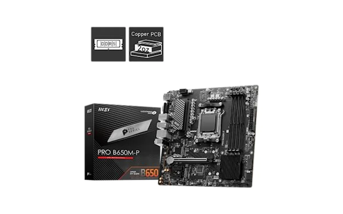
Direct Method: In-Game VRM Thermal Monitoring
Track VRM temperature during gaming using background sensor polling software connected to on-screen display (OSD) hooks. Best setup pairs HWiNFO64 with RivaTuner Statistics Server (RTSS). This renders real-time MOSFET temperatures directly over game graphics without alt-tabbing.
Voltage Regulator Modules feed current to CPU and GPU. High gaming loads drive power stages hard. If VRM heat sinks lack airflow, phases overheat, trigger emergency clock throttling, cause micro-stutter, or force emergency shutdown. Monitoring live telemetry identifies thermal bottlenecks before clock throttling occurs.
Telemetry Tools and Sensor Diagnostic Matrix
Motherboard makers assign different labels to voltage regulator sensors inside Low Pin Count (LPC) Super I/O chips. Look for these specific sensor labels in diagnostic tools:
| Motherboard Vendor | Primary VRM Sensor Label | Secondary / Phase Sensor | Safe Gaming Range | Throttle Threshold |
|---|---|---|---|---|
| ASUS | VRM, Motherboard Temp | MOSFET, VCore MOS | 45°C – 85°C | 105°C – 115°C |
| MSI | MOS, System Temp | VRM MOS | 45°C – 80°C | 105°C – 110°C |
| Gigabyte / AORUS | VRM MOS | Phase Temp, VRM | 40°C – 85°C | 100°C – 105°C |
| ASRock | VRM, Motherboard 2 | AUX / Super I/O Temp | 50°C – 85°C | 100°C |
Discrete power stages withstand 125°C to 150°C component maximums per silicon manufacturer specifications. However, motherboard copper traces, nearby electrolytic capacitors, and circuit substrate degrade rapidly if held above 95°C long term. Target VRM temperatures below 85°C during sustained gaming sessions.
Step-by-Step Setup: In-Game OSD with HWiNFO64 and RTSS
Follow this multi-step sequence to configure a live on-screen thermal read-out while running 3D applications:
- Install Core Telemetry Software: Download and install latest builds of RivaTuner Statistics Server (packaged with MSI Afterburner or standalone) and HWiNFO64. Run RTSS first to ensure background rendering hooks initialize.
- Launch HWiNFO in Sensor Mode: Open HWiNFO64, check “Sensors-only” box, and click “Run”. Let application poll all platform controller hub and Super I/O buses.
- Locate VRM Sensor Entry: Scroll past CPU core sensors to motherboard section. Locate “VRM MOS”, “MOS”, or “VRM” readout. If unsure how hardware sensors map on specific boards, verify how to read VRM temperatures in HWiNFO before assigning overlay hooks.
- Configure Overlay Properties: Right-click target VRM temperature entry, select “OSD (RTSS) settings”. Check box labeled “Show value in OSD”. Set line and column position (e.g., Line 2, Column 1) so reading does not overlap GPU frame-rate counters.
- Apply Polling Rate: Click global HWiNFO settings gear icon. Set “Sensor Polling Period” between 1000ms and 2000ms. Lower polling rates provide faster response but cause minor CPU overhead; 1000ms works best for stable gaming. Click OK.
- Test Display Inside Game: Keep both HWiNFO and RTSS running in system tray. Launch DirectX, Vulkan, or OpenGL title. Verify temperature value renders in corner of display.
Hardware Constraints and Missing Sensor Workarounds
Not every board contains dedicated thermistors. Budget chipsets (Intel H-series, AMD A-series, entry B-tier models) omit thermal diodes across voltage rails to cut manufacturing costs. Software tools cannot display physical readings if hardware lacks sensors.
When diagnostic utilities hide power stage telemetry, consult troubleshooting steps for a missing motherboard VRM temperature sensor. Fallback diagnostic paths include:
- Socket Temp Proxies: CPU Package or “Motherboard Temp” provide loose indicators. If ambient motherboard reading passes 65°C, VRM heat sinks likely exceed safe thresholds.
- Hardware K-Type Thermocouple: Attach thermal probe directly to heatsink fins or rear side of PCB behind high-side MOSFETs using Kapton tape. Connect probe to multimeter or external temperature monitor display.
- Non-Contact Infrared Thermometer: Remove case side panel during active gaming load. Point calibrated IR thermometer directly at MOSFET silicon packaging or choke array. Add 5°C to 10°C margin for internal die junction delta.
Thermal Diagnostics and Mitigation Measures
Sustained VRM heat during gaming stems from CPU package draw combined with stagnant case air. While graphics cards pull significant wattage, modern CPU power draws spike during high-refresh-rate gaming, physics processing, and background asset decompiling.
If on-screen readouts exceed 90°C while playing, systematically identify root cause:
- Top Radiator Exhaust Issues: Liquid cooling radiators mounted as top exhaust pull hot GPU exhaust air directly through radiator fins, slowing convective heat transfer from surrounding VRM heatsinks. Understand how AIO liquid coolers affect VRM airflow compared to downward-draft air coolers.
- Restricted Case Intake: Solid front panels starve intake fans. Higher case ambient raises VRM base temperatures one-to-one. Increase front intake fan curve relative to CPU temp.
- Aggressive Loadline Calibration (LLC): Over-volting CPU to stabilize overclocks generates massive MOSFET resistance losses. Switch LLC profile to balanced mode or apply negative core voltage offset to reduce motherboard VRM temperatures under load.
In-Game Verification Checklist
Verify these operational states during testing session:
- HWiNFO64 running with administrator privileges (required for direct Super I/O bus reads).
- RTSS detection level set to “Low” or “Medium” (prevents anti-cheat false positives in multiplayer games).
- Sensor polling rate aligned to 1000ms to eliminate micro-stuttering.
- Peak temperature under load stays under 90°C during extended sessions (2+ hours).
- Minimum delta of 15°C exists between VRM operating temperature and motherboard critical shutdown limit.
Frequently Asked Questions
Can MSI Afterburner monitor VRM temperature without HWiNFO64?
MSI Afterburner natively tracks GPU VRM temperatures if graphics board exposes sensors via driver API. It cannot display motherboard CPU VRM sensors on its own. Using HWiNFO64 to pass motherboard sensor data to RTSS is required for full motherboard monitoring.
Why do VRM temperatures stay high after closing a game?
Passive motherboard heatsinks lack dedicated fans. They rely on ambient chassis draft. Aluminum heat sink mass absorbs heat quickly but dissipates it slowly once gaming loads stop and case fans spin down to quiet idle speeds.
What is absolute maximum safe temperature for motherboard VRMs?
Discrete MOSFET packages withstand up to 125°C die temperature. However, sustained operating conditions above 95°C risk thermal degradation of adjacent board capacitors, reduce VRM conversion efficiency, and cause transient voltage drop. Maintain gaming loads below 85°C for long component lifespan.





Write Your Review
No reviews yet. Be the first to share your experience!